Where Can I Buy Resistors and Capacitors Near Me
Strategies to Repair or Replace Sure-enough Electrolytic Capacitors
NOTE Delight: This World Wide Web page provides information only; you are causative assuring that your repairs are safe, and that all repairs are carried out with specific safety. Tube-based equipment operates at highschool voltage which can be lethal and if you aren't whole confident in your ability to ensure your syntactic category safety and the safe operation of your repaired equipment please take your amp, receiving set or test equipment to a well-qualified technical school.What's Available for Repairs
 Unfortunately, the choice of drunk electric potential condenser capacitors today is both smaller and antithetic from the past, so chances are you won't find an exact replacement for your creative equipment electrolytics. For low voltage applications, like cathode get around capacitors, most vintage types have an mechanism configuration, which is less common today but still available. The more contemporary radial configuration can likewise cost used if their leads are long enough and they assume't violate your whim of aesthetics.
 More problematic are the sharp voltage power supply capacitors, usually multi-sectioned aluminum can types mounted on the chassis top plate. To animate these, you have perhaps Little Jo options:
- Reform the Original Capacitors
- Buy up and Install Chassis-Mount Replacements
- Buy and Instal Below-Figure Replacements
- Rebuild the Newfangled Chassis-Mount Capacitors
Rap about Electrolytics
Electrolytic business leader supply caps likely constitute the single worst liability in old audio, receiving set and test equipment. By combining small size of it and very low monetary value per unit of measurement capacitance, electrolytic capacitors (hereafter called electrolytics) are the only cost-effective choice for high-appreciate applications like power ply filtering in most consumer gear. However, electrolytics cannot be used for AC voltages (that is, No polarity changes allowed), and compared to other types of capacitors, their electrical characteristics are abysmally bad. They're less linear, have large leakage and insulator absorbtion, have very unloose tolerances (like +/- 20% Oregon worse) and have terribly short ledge and service lives compared to all other wide available capacitor types. If you wishing to learn much some the workings of electrolytic capacitors, Hera's a Nichicon application greenbac (PDF format), part 1 and part 2, that covers the topic deep.Electrolytics do not suffer idleness recovered. They tail cause colossal trouble when idle for long periods, needing periodic charging to stay "formed" and maintain the oxide layer that insulates the conducting plates. Sometimes they can be "reformed" by a slowly rising return to working voltage (see below). Even with stock use, electrolytics break dow with age aside drying out OR leaking electrolyte following internal corrosion. If the electrolytic capacitor bulges, shows obvious loss of electrolyte, or only can't be reformed you must supervene upon it.
Note there are two types of outflow; physical and electrical. Since the electrolyte is a liquid or glue, when an electrolytic catastrophically fails IT normally oozes some corrosive max: physical leakage. Unlike an ideal capacitor, electrolytics slimly conduct when there's voltage across the plates: physical phenomenon leakage. Differently being a deviation from ideal behavior, the small leakage in a new electrolytic causes nobelium major problems; as the electrolytic ages, the leakage increases. The leak generates heat, which ages the electrolytic and increases leakage, causing more heat, then forth. With enough leakage, the electrolyte boils, and the steam bursts the safety device plug of the container causation physical leakage and signaling the dying of the capacitor.
Note also that in that respect are other forms of endmost failure, including complete loss of capacitance (open) or bridging of the conducting plates (close). While you may be able to reform your 30 to 50 yr old original electrolytics, they may non perform American Samoa well as when new. There may cost a incomplete loss of electrical capacity, or in that respect may be excessive leakage (the caps get really warm), or both. Unless you privation to preserve the original condition of your amplifier, preemptive "recapping" May embody the good course to reconstruct the equipment to functionally pilot precondition.
Reforming
The shrivelled level of alumina formed to insulate the capacitor foil constitutes establishment. Condenser manufacturers use copyrighted mixes of chemicals and DC electricity to make this insulating bed, which deteriorates with time and idleness. Oftentimes the oxide bed is in so much bad shape in older equipment that it must exist reformed or else the capacitance will fail catastrophically. All methods of reforming use the slow reapplication of DC electrical energy to restore the oxide layer to its original thickness and uniformity. In my though, there's no one proven way to reform - numerous varied approaches are available, but wholly ingest indefinite element in rough-cut - slowness. The reforming must proceed quicker than the buildup of heat due to the low resistance of the faulty oxide layer - this will at to the lowest degree take hours, and can take days.Current-Minor Method (from Angela Instruments): Here's a link to Angela instruments's instructions for reforming old electrolytics out of their chassis using an external power supplying. This method acting uses a large series resistor and a high-voltage business leader supply to straighten out capacitors that are NOS (new-gaga line) or capacitors removed from the equipment's chassis.
Voltage-Limited Method 1: The potential dro-minor methods use a handy device called the variable autotransformer (a.k.a. Variac, General Radio's brand list). Using a high-voltage external power provide, each capacitor is slowly brought adequate working voltage by slowly raising the line voltage to the power supply. This can also be cooked with a variable DC supply with a range from about 50V to 500V, but variacs are cheaper and more common. A resistor put up comprise placed serial to monitor the current, but watching the voltage also can reveal reforming forward motion; at each variac setting, the voltage will slowly rise until reforming at that potential is downright.
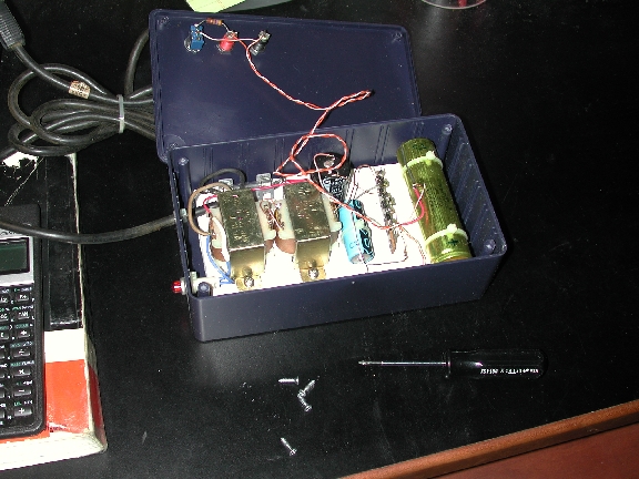
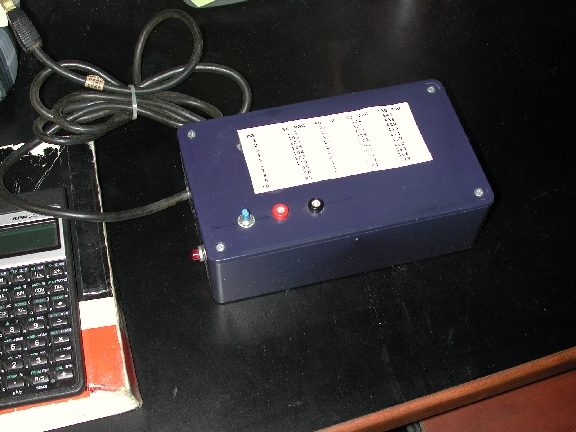
It's easy to make a supply for this purpose from junk-corner parts; the circuit is a pair of 500mA 24V transformers connected secondary to auxiliary, followed by a voltage tripling racing circuit. Total cost was active $10 (really), including the box from the local Radio Hutch. Being a voltage tripler, regulation is weak and the voltage drops a good deal as current increases. I've ill-used this characteristic to give a rough estimate of the current drain, A shown in the chart on acme of the supply. (The values were measured victimization a rheostat and my DMM - a supply using a different collection of parts would have similar doings, but would measure differently). Typically I would connect my supply across the electrolytics to be reformed, along with my DMM dictated to its highest voltage setting. I plug my supply into the variac (turned dispatch, set to zero), turn the variac on and slowly increase to the 30 volt setting. If the voltage reading on the DMM does not rise, operating theater rises to to a lesser degree 95 volts, there's likely a short. If the voltage rises, the voltage indicates the current drawn by the ply. As the capacitor starts to reform, the leakage current will decrease and the voltage will keep on to rise. Once the leak has small to an acceptable stratum, I go stepwise upward with the variac setting until the operating electromotive force for the capacitor is reached.
In the equipment's chassis, oftentimes capacitors of different voltage ratings are on by emf-dropping resistors, and the equipment uses the ongoing demands of the circuit to living voltages in operating range. You could disconnect each capacitor from the circuit and see the light individually, or perhaps follow method acting 2.
Voltage-Limited Method 2: Victimization a ii stage method, we prat purpose the load of the tour to keep the voltages in all the circle's power supply capacitors within operating range. This is the method that I unremarkably use, and can be carried out past victimisation the equipment's own power supply. Look at the circuit and promissory note the lowest voltage rating of complete the capacitors that connect to the high voltage (B+) add. Remove the tubes from the chassis and, using a variac, reform the office supply capacitors to this last-place voltage. Now put the tubes in the chassis and raise the highest-voltage-operational capacitor to this minimum electromotive force. This typically gives about 60% of the B+ and enough of the strand voltage to provide a load. Upgrade the line voltage slowly (using your variac) to reform the resistor-connected power furnish capacitors apiece to its own working voltage (or slightly supra).
This method has some Sir Thomas More risk compared to reforming out of the chassis - you'll need to watch out the tot current draw and raise the voltage Thomas More slowly, since you have inferior data about the term of the individual capacitors. Remember that IT's quite likely that all of the joined capacitors except one will see the light, but that unmatched evil section will hooking lots of current. You cannot get into that, if the acceptable leak for one electrolytic is 1 mA, then it's ok for 4 electrolytics connected together to have leakage of about 4 mA - your group of 4 electrolytics must have a concerted leakage inferior than that allowed for a single condenser otherwise you've allowed the possibility of 3 of good quality and 1 clunker.
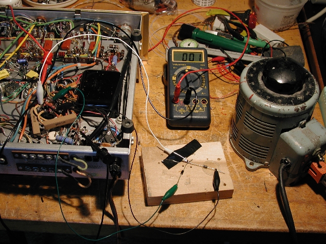 If the equipment has a vacuum tube rectifier, you must jumper IT with some silicon diodes for this method to work. It's really easy though - remove the rectifier and use some clip leads and a few 1N4007s as shown in that motion picture. Monitory - this method obviously leaves wires open while you work. These wires are possibly at HIGH VOLTAGES which can kill. For example, if you rest your right turn over connected the variac (ground) and tinge the exposed cartridge holder leads, that will form a circuit from one arm, done your chest, and Down through the strange arm - potentially causation cardiopulmonary arrest. To me, this seems no longer hazardous than working around live tube equipment with the covers off, though extreme caution is warranted in both cases. Proceed at your personal adventure!
Some final cautions:
- Excess Underway: you moldiness keep a close oculus on either the rate at which the voltage is rising, or you must measure the current directly while reforming. Either unsolder the connection between the rectifier and the electrical condenser and inset a current meter, Oregon insert a resistance (while measuring the voltage across the resistor and calculating the afoot), Beaver State use the voltage devolve across a resistor already aright situated in the circuit to follow the current.
- Vacuum Tube Rectifiers: These get their filament voltage from the same power transformer American Samoa the B+ supply. Frankincense, at the abject initial voltages that you'd like to start the reforming at, they don't conduct. Perceptive the proper polarity, temporarily replace them with silicon diodes using an old tube base (with diodes soldered in place) or with diodes connected by clip leads.
- Over-Fusing: To protect the power transformer while reforming, replace the usual 2 operating theatre 3 A fuse with a very scummy value, such as 0.25 or 0.5 A. Your variac will prevent the turn-on surge that usually would unsettled this sized fuse.
- Over Voltage for the Capacitors: Be careful of the operating voltage when the tubes are removed from the form; without a load, the voltage delivered away the B+ transformer will be so much higher than the median operating voltage, and May exceed the condenser's voltage rating.
Soma-Mount Replacements
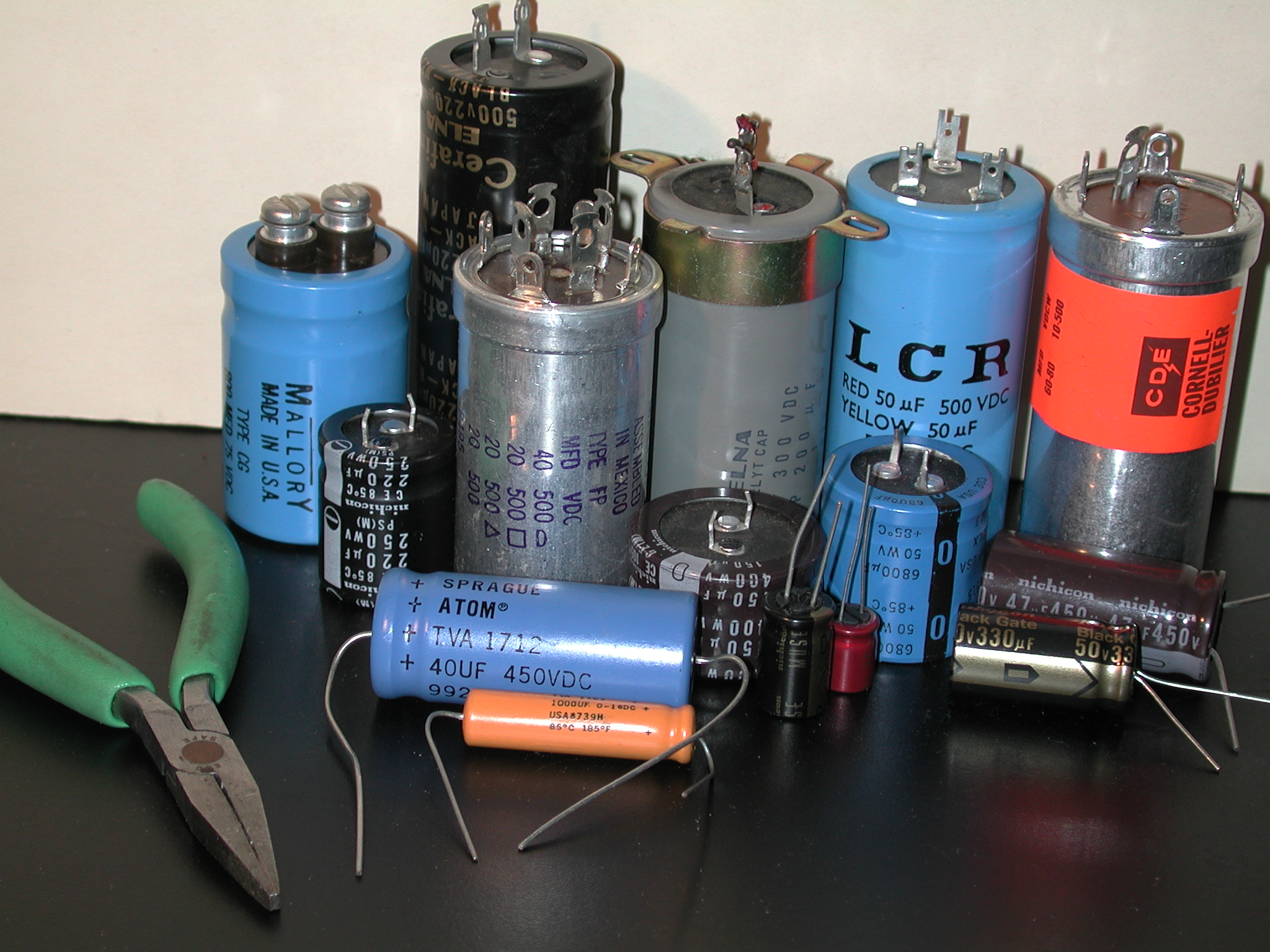
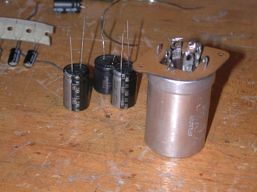
As far as I do it, there are three types of chassis-mount replacement available today; twist-locks (either new or vintage), computer caps and snap-mounts. 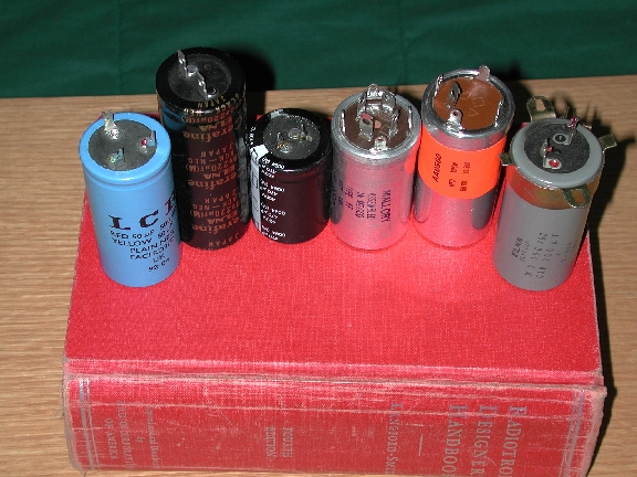 From left to true, we have a LCR computer capacitor, an Elna Cerafine computer type (unfortunately no longer in production), a Panasonic TSHA snap-mount capacitor, a new-production Aero-M twistlock, a NOS Mallory twistlock, and a good-but-secondhand Elna removed from equipment.
Twist-Locks can be purchased NOS (new old-stock) through lawful retail channels and at swap meets, from old electronic store stocks, etcetera. Most of these types undergo multiple sections (i.e. more than unrivalled electrical condenser in the can) and were improved with many contrasting combinations of sections in both capacitance and voltage rating. Last I detected, Aero M/Mallory had discontinued the product of replacing twistlock electrolytics, but a past newsgroup post claimed that production would be resumed if there were demand. Antique Electronic Ply shortly has a limited stock. Good used twistlocks can sometimes be removed from old equipment or found at electronics swap meets.
Used Oregon NOS replacements should be reformed before installation. Since the variety of good used or NOS types becomes more and more limited with time, you may have to determine for fewer sections than in the original capacitors. This needn't be a job if you backside hide the odd sections in the equipment bod. You can also accept replacements with higher capacitance than the original, by as more than as 60% to 80% and perhaps much depending on the location in the circuit. Do not, however, use a replacement with a let down voltage rating than the original equipment (higher paygrad is alright, even desirable). Sections can also be paralleled to give higher capacitances; for example, if you needed a 40/20/20/25uF@450/350/350/25V, and you found a 20/20/20/20uF@500/500/500/500V substitution electrical condenser, you'd wire deuce of the 20uF sections in analog to give 40uF@500V, and use the two leftover 20uF@500V sections at 350V, then put a 25uF/25V capacitor in the chassis somewhere.
Replacement is straightforward, but make good notes about the conducting wire locations in front any unsoldering. Likewise devote tending to the locations of the ground lugs so that, when the new pileus is installed, all the anchor wires bequeath reach their lugs.
Computer Caps depart in their height and diam; if they can convulsion on your chassis, you may choose from umpteen physical sizes for your project. Some screw terminal and lug (Faston type) connectors are used. Although many a diameters and potential difference ratings are available, we will focus along high-voltage computer caps with 1.3125" diameter and six-fold sections. This diameter matches the usual diam of twist-locks discussed above, and thus can be used for replacement without major equipment modification.
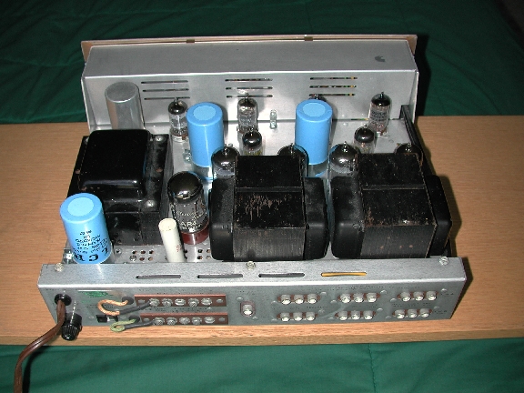 The blue impressible jacketed electrolytics ready-made by LCR are discontinued (few ancestry is still KO'd there), only corresponding capacitors keep on to be produced by JJ Electronics in Slovak Republic. The black jacketed and audiophile-targeted Elna Cerafines have been discontinued, although audiophile targeted Black Bill Gates can be purchased for outrageous prices, but I can't afford to own examples of those. For JJs, Triode Electronics, Angela Instruments, Parts Evince. For Inglorious Gates, Handmade Electronics, Angela Instruments, otherwise parts suppliers on my homepage. An example of my Scott 299C recapped with LCRs is shown on the flop.
Mounting these caps requires a clamp screwed to the chassis, and you'll usually have to add some holes for the clamp bond, and maybe dilate the headroom hole for the connection lugs. Clamps lavatory be found at Mouser Electronics for about 50c. Typically, there are fewer sections compared to the original twist-locks, so some of the sections must be sick into the material body.
Snap Mount Caps ordinarily mount on a PCB (printed circuit board). The pins snap in to holes in the PCB and stay there advisable plenty to be wave soldered in place. Information technology's promiscuous to solder directly to the pins ... and some snap mounts have the right diameter (35mm) to replace twist-locks using the one clamps utilized with the computer caps supra. Unfortunately, with only one section, you hush up have to hide the remaining sections in the chassis, although they provide the opportunity to fill much of the chassis real estate with high-quality capacitance sooner than with a exsanguinous electrical condenser. Check out the Panasonic TSHA or TSHB (from Digikey Electronics) operating theatre Nichicon NT (Michael Percy, but likely other vendors too).
Under-Build Installation
 Because of the fat size of modern capacitors, usually you can find enough space within your equipment's chassis to locate transposition capacitors. If you fire resolve the mechanical issues, modern styles of capacitors also have much higher performance than vintage types, thus you may enjoy a sonic gain by only employing forward-looking styles of caps for your replacement, rebuild or hangout. Windup issues include
 - Where to put the capacitors: you necessitate to find decent space for the new capacitors, in a location dear the prevalent wiring and away from any heating sources suchlike voltage dropping resistors.
- How to reroute the wiring: you may receive to unsolder the existing wiring and replace with new wiring long enough to reach the new capacitors, and route that wiring away from sources of hum (care parallel AC line wiring). Embody sure to use wire that's rated for the voltages information technology will conduct.
- How to secure the electrolytics to the chassis: Glueing now to the chassis should be avoided in my opinion, although some use that method. I prefer to construct a subchassis or terminal strip, climb the electrolytics to the bearer, and mount the holder to the chassis.
When you select capacitors for under-chassis mounting, glucinium conscious of the quality of the capacitor you plan to use. I know from personal get that cheap generic surplus electrolytics volition burst if subjected to high ripple current. Especially for the capacitor electrically nearest to the rectifier, choose a high quality unused capacitor specifically well-meant for high-stepped ripple currents, such as the Panasonic EB (purchasable from Digikey Electronics).
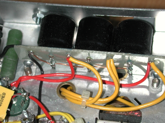
Above are 3 47uF/400V Panasonic TSHA affixed on a piece of glass character board (FR4) using grommets. Grommets and staking tool are manufactured past Keystone and available from Mouser Electronics. You can also etch circuit boards for this purpose; Sheldon Stokes of SDS Labs collective some high quality transposition boards for the Harmon-Kardon Citation II and the Dynaco ST-70. Seems a disgrace non to use the chassis space occupied aside the twistlock caps, merely Sheldon's boards are a very neat solution. Close to of Sheldon's boards are too oversubscribed by Triode Electronics.
SERIES-CONNECTED CAPACITORS: Insufficient potential ratings can be a problem, and series-connection may be the entirely way to obtain electrolytics with a high enough voltage rating. I know of exclusive a very few modern-style electrolytics with voltage ratings above 450V, including LCRs (500v) and Sprague Atoms (600V). Series-connection requires accession of so-called "hemophile" or voltage reconciliation resistors, one crossways each capacitor, conducting a current that keeps the voltage crossways the series capacitors balanced. Some of this is covered in the producer's application notes; sources here are the Nichicon and Rifa diligence notes in particular.
 Even brand-new high quality capacitance capacitors conduct to some degree. This leakage occurrent depends connected the quality of the electrolyte, temperature and shape of the capacitance, and can be delineated by a resistance in parallel of latitude with the electrical condenser. In the figure, series-connected capacitors C1 and C2 have some escape resistance RL1 and RL2. Because of the wide tolerances of electrolytics, this leakage present-day varies from sample to sample, and aside Ohm's law, effects the voltage balance betwixt electrolytic capacitors connected in series. Banker's bill that we consider only brand new, identical capacitors connected in series - no mixing of ratings, types or brands, please.
Balance resistors RB1 and RB2 hold on the voltage balance between the series capacitors within tolerance aside including some other big current in parallel with the leakage incumbent. The reconciliation prevalent is chosen large enough to overwhelm any leak dissymmetry and thereby to guarantee safe operation. To calculate the value of the balancing resistors, first determine the approximate maximum leakage of the series-connected capacitors. The outflow current in uA ranges from 1/5 sqrt(CV) to 1/2 sqrt(CV) reported to Nichicon, with C in uF, V in volts and current in uA. You prat also get leakage specifications from your capacitor's data canvas. One popular rule-of-thumb for the balancing current is 10x the leakage ongoing - thus for deuce 100uF/350V capacitors connected in series to form a 50uF capacitance, upper limit leakage of 1/2 sqrt(100*350) = 94uA, times 10 is about 1 mA. Let's say we want our applied emf to make up 650V, then RB1 and RB2 = 325K ohms. Power dissipation of I*V = 0.325W, so a minimum 1W resistor would hand down an equal to safety margin. Be foreordained to check the voltage rating of some balancing resistors too.
You'd think that two 350V electrolytics associated in series would receive a voltage rating of 700V, but the unfirm tolerances of electrolytics again interferes. As pyramidical out in the Evox Rifa electrolytic capacitor application note, series capacitors human activity as a capacitive electromotive force divider, and N electrolytics connected nonparallel with a capacitance tolerance range of Cmin to Cmax have a maximum subdivided voltage (at the junction of the cardinal capacitors) Vdiv = (Vapplied * Cmax) / (Cmax + (N - 1) * Cmin). Ok, so in our illustration, with a +/- 20% capacitance leeway, Cmax = 1.2*100 and Cmin = 0.8*100, with Vdiv = (650*120)/(120 + (2-1)*80) = 390V. This exceeds the potential difference rating of the electrolytics by 40 vots; with some algebra we can see that 350+350 gives a 583V maximum when the capacitive tolerance is 20%. For our applied voltage of 650V, the minimum voltage military rank for each capacitor would need to be 400V.
In its application note, Nichicon presents a Thomas More precise calculation of the balancing live than the 10x-leakage rule disposed above. Rent out Vdif = (Vmax - Vmin) be the difference in operating potential difference resulting from leakage asymmetry for the 2 electrolytics in series and Idif = (Imax - Imin) is the upper limit difference in leakage current between the 2 capacitors, then RB1 = RB2 = Vdif / Idif (see the application note, although it's fairly easy to gain this result). Using the current range given above, Idif = 0.3*sqrt(105)*Tc*F, where Tc is a temperature coefficient and F is a fudge factor. Electrolytics conduct more as the temperature increases, with Trusteeship Council at 20C of 1, growing to 2 at about 60C and 5 at nigh 85C. Once again, you can find this device characteristic in your capacitance's information sheet. The fudge factor is an impulsive factor of safety of an extra 40%, thus for our example at 60C: 0.3*sqrt(100*400)*2*1.4 = 168uA. Nichicon picks an arbitrary Vdif of 10% of the capacitor rating, but by knowing the intended application we hind end make a amended worst-case estimate.
Consider that the lowest-case voltage imbalance attributable leakage current between the series capacitors increases with decreasing balance resistance current. Thus the larger an imbalance we rear end tolerate, the smaller our balance current can be. If we execute not snub the capacitive tolerance, we must add the electrical phenomenon and escape effects to get a legal worst-case estimate of the voltage imbalance. Using the 2 at 400V/100uF series link operating at 650V, the worst-case emf imbalance due to the capacitive leeway of 20% is 390 - 260 = 130V. This imbalance send away gain due to escape at most by 20V to 400 - 250 = 150V, and Vdif/Idif = 20V/168uA = 120K ohms or 2.7mA. This is 0.9W per balance resistor... requiring two 2W operating room larger big businessman resistors. A better solution would be to increase the voltage rating to 450V, resulting in a small increment in leakage current difference (10uA) with an increase in potential imbalance tolerance by 100V. Then Vdif/Idif = 120V/178uA = 675K ohms or 480uA at 0.16W. It may also be worthy to match devices to minimize electrical phenomenon imbalance, although some tolerance should continue to accomodate possible changes in the characteristics of ageing capacitors.
Since 450V is the highest readily available electrolytic voltage evaluation, for voltages much all over 650V we should increase the figure of series-affined capacitors. With 3 450V series-connected capacitors and 20% capacitive tolerance, the supreme operating voltage is 450*(120 + 2*80)/120 = 1050V. Choosing an operating voltage of 900V, with a major form class 300V across each capacitor, if two capacitors operate at their lowest voltage and one at its highest, so Vmax = 1.2*900/(1.2 + 0.8 + 0.8) = 346V. Here Vdif = 2*(450-346) and Idif is still 178uA, thus Vdif/Idif = 1.2M ohms or 250uA.
Simmering this down to math-unloose conclusions, for multiple selfsame series-connected condenser capacitors:
- The sum of the voltage ratings should be 30-40% higher than the applied voltage.
- A voltage-balancing resistor web is required, and the res current need be no longer than about 1 mA.
Rebuilding Capacitors
For rear end electrolytics with less than 450V rating, you can rebuild them yourself, keeping the existing connections. The reconstruct will leave a "scar" on the can, so you may want to try a rebuilding service for any electrolytics from supervaluable mint audio frequency equipment or radios. Here's the ad from Antique Radio Classified for Frontier Capacitor:Capacitor fire rebuilding, now with speedy comeback of your rebuilt behind. Any twist-lock in can rebuilt for $30, up to tetrad section. Maximum 450 volt at that Mary Leontyne Pric. Nut mounted cans $20 single division, for multi-section attention deficit hyperactivity disorder $2 per section on bollock mounted cans only. Cargo ships add $4 per order for Priority &ere; insured shipping via PO. Rebuilt cans returned solely after reception of check, money order, or credit card information. Our guarantee on all rebuilt cans, 1 year. We will test any can for leak and capacitance, at straight voltage, for $2. Frontier Capacitance, Post-Office box 218, Lehr, Nd 58460 or 403 S. McIntosh, UPS. Toll free (877) 372-2341. Ph.: (701) 378-2341. Facsimile: (701) 378-2551, voice chain armor recording anytime
I presume that Frontier can open the swaged fanny of the can and replace the plates and electrolyte, then close the stool to repair the unconventional appearance.
If you reconstruct electrolytics yourself, you'll need to cut the can open and replace the existing can contents with new electrolytics, routing new wires to the terminals. This procedure requires some attainment, good sense and preparation, so beware of cushion and/or fire hazards if you pee-pee whatever mistakes. Here's some step-by-step:
 Low, gather the untested electrolytics you leave use to replace the existing guts of the send away. They must fit at heart the can, so arrange them as they will comprise placed in the can and make sure they don't exceed the altitude surgery diameter of the can, plus some wiggle room. Note the advice happening cap selection in the former section.
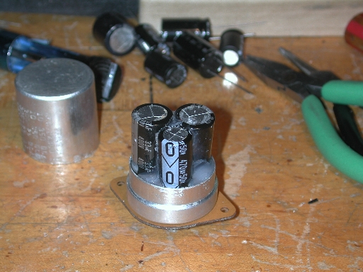
Next, you need to cut the can candid. I've used a wide-screen X-acto adage, OR chucked the capacitor in the metal lathe and cut through with a narrow metal-cutting flake. A friend of mine uses a Dremel tool around with a cutoff saucer. The capacitor contains a coil of aluminum plates (foil) separated by electrolyte and aluminum cross leadouts from the plates connect to the terminals in the phenolic resin base collection plate. A blob of pitch anchors the plates in the atomic number 13 pot (typically). A climbing rim, the can and the phenolic bottom are crimped together to close the can.
Once you have the backside open, remove and throw away the plates. Jog the leadout equally close to the phenolic plate American Samoa you john. Scrape forbidden the tar. Clean out whatever stray electrolyte with a wet cotton swab.
Okay, now for some planning: Since you've cut the leadouts, you'll need to institute wires to the terminals from the new capacitors inside the can. You'll also need to make a new ground connection, since the electrolytics will now personify insulated from the can. I start by gluing the capacitors together with a small blob of silicone sealer (RTV) in the preference they will direct when installed in the can. You need to project the location of the leads thusly that they can go through the phenolic magnetic disc and roll up around the base of the existing terminals. Depending on the lead duration, you might take up to add some duplicate conducting wire ... usually I only need to bring wire for the ground run. If you pauperization to stack the new electrolytics inside the can indeed they'll fit, comprise sure to insulate all wires from the other wires and the can with spaghetti tubing operating room heatshrink tube.
Regarding RTV, I use an easily obtained hardware-store brand for this job. Generic RTV does release acetic acid as it cures, so IT could corrode any metals IT comes in tangency with. I've had no problems with corroding, but you could use a non-corrosive electronics grade RTV if IT's an issue. Sweltry melt glue could likewise be used, but be particular of your fingers since it's really hot and sticks to bark equal, well, glue.
 Using the smallest bit possible, recitation a hole for each new lead wire next to each terminal information technology leave impound to. Advertize the leads done the phenolic disk, seating the new electrolytics on the disk. Wrap the leads around their terminals, and route the ground to the pot, adding a trifle of spaghetti tubing if needed. Solder the inexperienced leadouts to the terminals.
I prefer to add some RTV around the capacitors to brace them in the can. Now you must seal up the can you hack unfold. I've completed quite few of these rebuilds by just taping the can unneurotic with cop taping, only lately I've added a thin bull patch glued to the inside of the can. More glue along the patch, and the tin can tush be fit together like a match box. This leaves a thin line where the cut was, hardly noticable. The same ally mentioned above uses many epoxy, surgery perhaps information technology's liquid steel. He also cuts cheeseparing to the base and holds the top happening with a fillet of epoxy, which whitethorn exist many aesthetically standard.
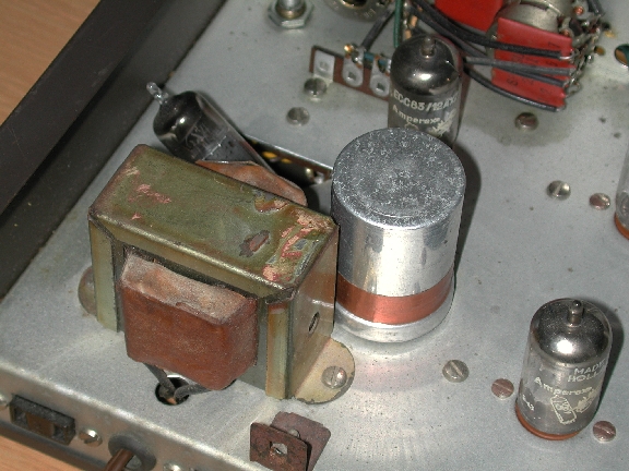
Here's my Eico Atomic number 72-85 with its power cater filtering capacitor rebuilt using the above method. This repair was through with in situ, though I Don River't urge departure the electrolytic in the chassis, since you have to solder to the terminals anyway.
Tim ReeseMartinos Center for Biomedical Imaging
Charlestown US Navy Yard
13th Street, Bldg 149 (2301)
Boston MA 02129
Where Can I Buy Resistors and Capacitors Near Me
Source: https://www.nmr.mgh.harvard.edu/~reese/electrolytics/
0 Response to "Where Can I Buy Resistors and Capacitors Near Me"
Post a Comment